Global Hawk Maintenance & Operations Complex, AAFB, GUAM
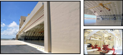
The project is a concrete high-bay hangar which includes covered aircraft maintenance space, maintenance support space, supply/tool room/support section, squadron operations, classified storage, maintenance operations center, space for launch recovery element, and secure work areas all in support of the Global HAWK surveillance program.
The work includes reinforced concrete footings and floor slab, pre-cast concrete arch roof, pre-cast architectural concrete, CMU, fluid applied elastomeric roofing, steel sliding hangar and tail doors, building finishes, hangar floor coating, fire suppression/detection system, intrusion detection system, overhead electric cranes, A/C, and electrical/communications systems. Site work includes the connecting of utilities, storm drainage system, sewage lift station, pump building and water supply tank, asphalt and concrete pavement, exterior lighting and incidental site work.
Notable Features:
Civil, Structural, and Architectural:
- Site Area: 25 Acres
- Area for Grading: 10 Acres
- Cut Volume: 33,800 CY
- Fill Volume: 5,000 CY
- Disposal Site: Estimated as off base. Actual, we are currently utilizing the AAFB Landfill.
- Relocation of JP8 Fuel line that through the project site.
- Removal of 620 CY of PCB Contaminated Soil
- Relocation of Injection WellM
- 241 Probe and Grout Locations from 17′ to 27′.
- 2,700 LF of Site Waterlines (4″ to 18″ diameter)
- 1,080 LF of Site Sewer (3″ to 6″ diameter)
- 420 LF of 24″ DI Sewer Pipe
- 2 Sets of Pumps for Lift Station and Holding Tank Wet Well
- 1,560 LF of RCP Storm Drain Pipe
- 3,800 CY of Sewer and Waterline Trenching
- 4,670 CY of Electrical Duct Trenching
- Volume of Concrete: 17,000 CY
- Quantity of Rebar (#3 – #11): 1,162 MT
- 11 Post Tension Tie Beams
- The main structure is a pre-cast folded plate design. We have a total of 63 each Open Segments and 22 each Closed Segments. The height of the segment is 6′ and the width varies from 9′ – 12′. The overall length of each segment varies from 28′ to 63′. The heaviest segment weighs approximately 52 tons. The casting of these segments will be done on site (see the attached drawing for casting bed locations). The segments will all be direct pour. We will be utilizing the Manitowoc 888 for the erection of the pre-cast folded plates. We will utilize the Manitowoc 4100 for loading out of the pre-cast beds.
- Building Area:
- Hangar: 4395 SM
- Support Building: 1134 SM
- Fire Pump Building: 142 SM
- Additive Items (Nose Dock, AGE Structure): 292 SM
- Total: 5963 SM (64,185 SF)
- Building Height: 19.51 M (64′)
- 2 EA 86,000 GAL Water Storage Tank: Glass Fused
Coating (20′ Inside Diameter x 38′ H) - 1 EA Concrete Holding Tank: 140,000 GAL Capacity
- 1 SET of Hangar Door System (8 leaf of 23’H x 37′-6″W)
- 1 SET of Tail Door System
- 2 EA Stainless Steel Davit Cranes
- 3 SETS of Monorail Hoists (3 Ton Capacity)
- 2 SETS of Overhead Electric Cranes (5 Ton Capacity)
- 2 SETS of Fall Arrest System
- 1200 SF of Chain-link Roof and Wall Enclosure at Mechanical Area
- 600 LF of Interior Pre-Fab Trench Drain (Fiberglass)
- 53,000 SF of Hangar Reflective Floor Finish
- 120,000 SF of Elastomeric Roof Coating
Electrical
- Main Feed: 1-1500kVA, 13.8V-480Y/277V Pad-mounted Transformer
- 600kW, 480/277V Diesel Standby Generator Set
- Separate 75kVA, 13.8kV-480Y/277V Pad-mounted Transformer to feed Fire Pump Building separately.
- 2 EA Main Switchboards to feed the various loads
- 2 EA Pad-mounted Switchgear.
- 4 EA 480V Power Stations. 2 on each side of the hangar to serve special power connection requirements for the aircraft.
- Lightning Protection and Grounding Systems:
- 60 EA copper air terminals above the roofing plus 9 EA High Mast air terminals.
- 50 EA Ground Receptacles within the hangar floor for aircraft grounding system requirements.
- 65 EA Ground Rods as a ground loop within the building.
- Fire Alarm System
- Foam Suppression and Alarm System that will utilize a combination of UV/IR Flame Detectors within the Hangar Bay area.
- PA System
- Data/Phone (Communications) System
- DDC System to control and monitor the PACU
- Trenching of approximately 2 miles of communication and power duct lines.
Mechanical
- 3 EA Fire Pump, Horizontal Split Case Centrifugal, 2000 GPM w 3000 Gal Double Wall Above Ground Storage Tank.
- 1 SET Fuel Storage Tank, 4000 GAL Convault w/SSTL primary tank and accessories for the generator.
- 4 EA ACCU, 80 Ton Capacity, Stainless Steel Panel
- 4 EA AHU, 20,640 CFM, Double Wall SSTL Panel
- 2 EA Ductless DX Split Type, 12000 BTU Capacity
- 25 EA Variable Air Volume (VAV)
- 12 EA Foam Generator with Horizontal Bladder Foam Concentrate Storage Tank with 175 PSI Working Pressure
- 2 EA Surge Tank for Fire Pump Piping Line 80PSI
- 2 EA Surge Tank for Wet Pipe Sprinkler Riser 10PSI
- 1 EA Surge Tank for Foam Suppression System 10 PSI
- Radon Piping
- Plumbing Piping and Fixtures
- Wet Pipe Sprinkler System
- FM 200 Foam Extinguishing System at Support Area
- Hangar Exhaust System
- Compressed Air System
Guam Contractors’ Association 2009 Excellence in Construction Awards
Industrial $25 to $100 million Category Winner